Installing the Advanced Flow solution
Download as PDFThe Advanced Flow solution pairs a Logger WD-68/4WD datalogger with a level radar and a surface velocity radar to measure flow in a manhole or channel. This article covers activating the datalogger and mounting the bracket and sensors on site.
1. Activate Deploy Mode
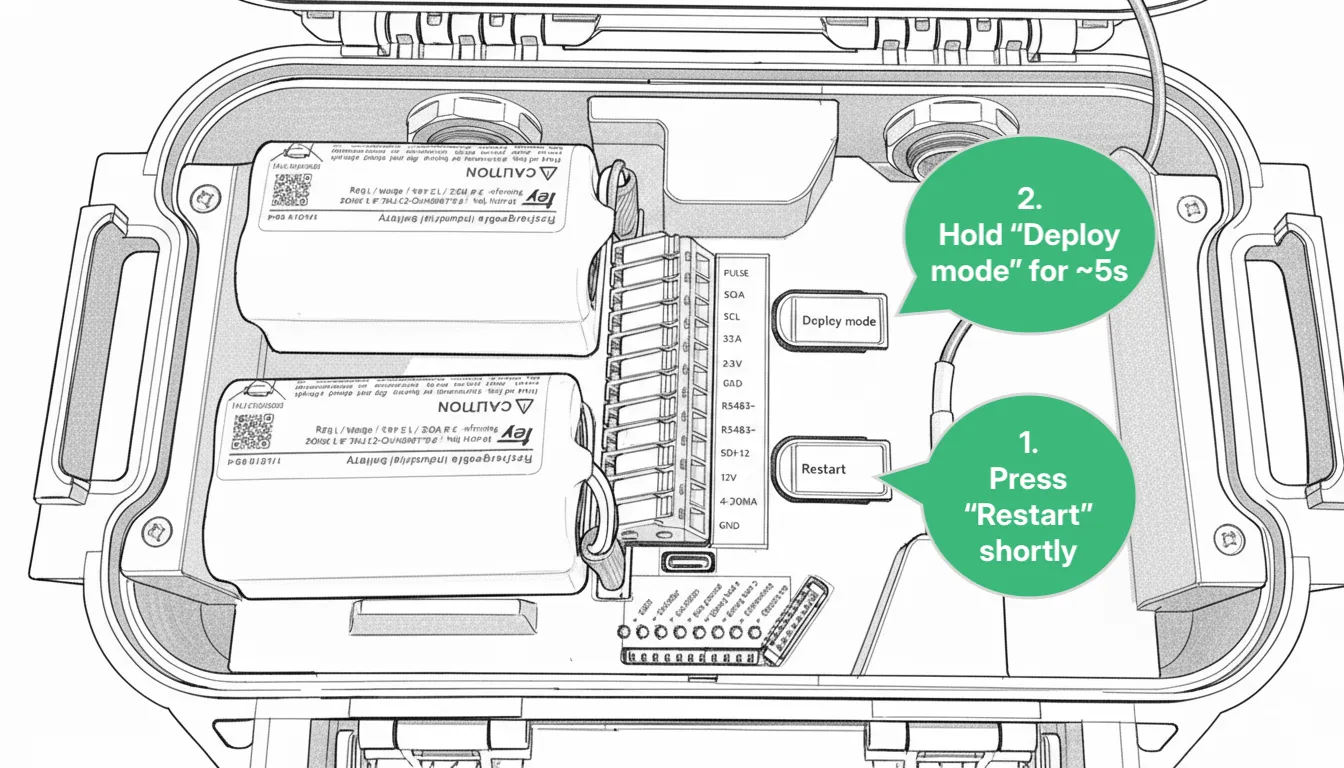
Section titled “1. Activate Deploy Mode”The first thing to do when arriving on the installation site is to activate Deploy Mode on the Logger:
- Press Restart shortly.
- Hold Deploy Mode for approximately 5 seconds. When the LEDs flash quickly one at a time in a repeating pattern, Deploy Mode is activated.
For the next 1 hour, the device measures every 30 seconds and transmits every 5 minutes. After 1 hour, it reverts to the transmission and measurement interval configured in Consibio Cloud.
Activate Deploy Mode as the first step so the Logger starts connecting immediately — it scans the local network operators and selects the most optimal one. On the first attempt, this can take a few minutes.
2. Mounting instructions
Section titled “2. Mounting instructions”2.1 Preferred installation: at the inlet
Section titled “2.1 Preferred installation: at the inlet”The preferred installation is to mount the fixture above the inflow:
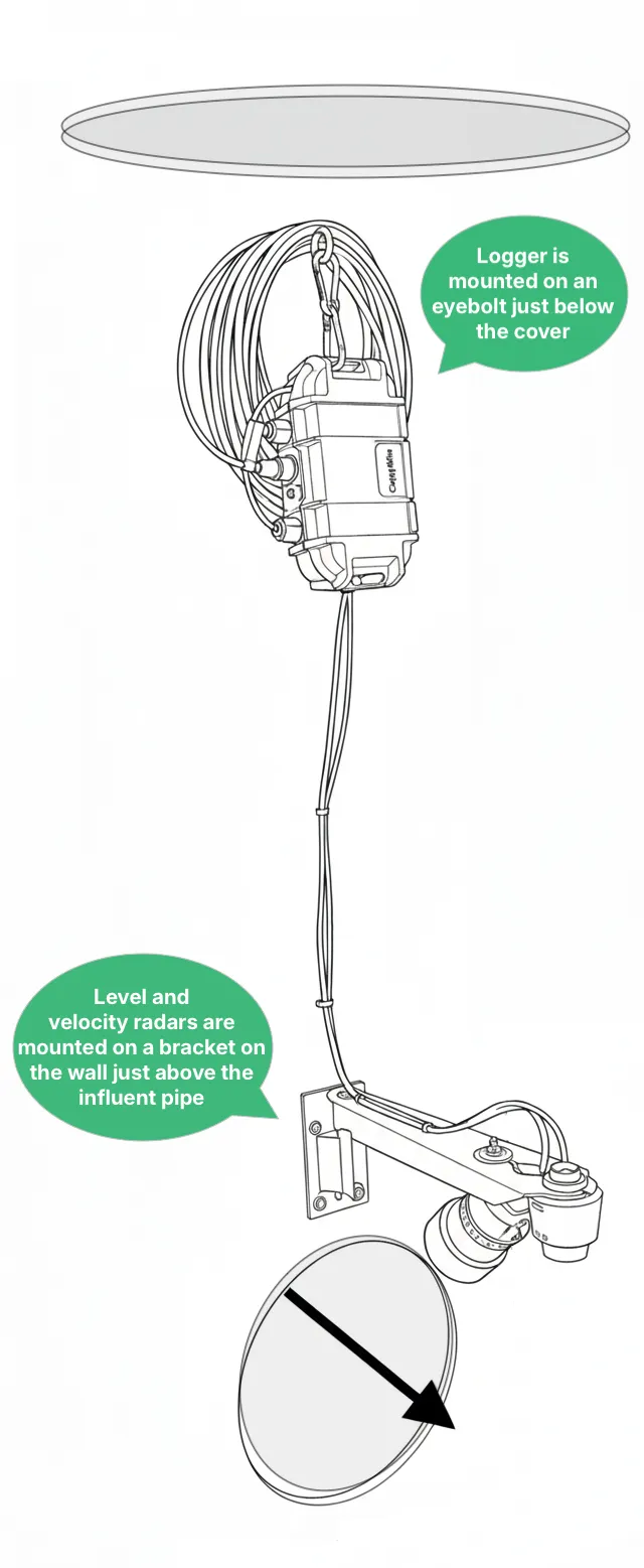
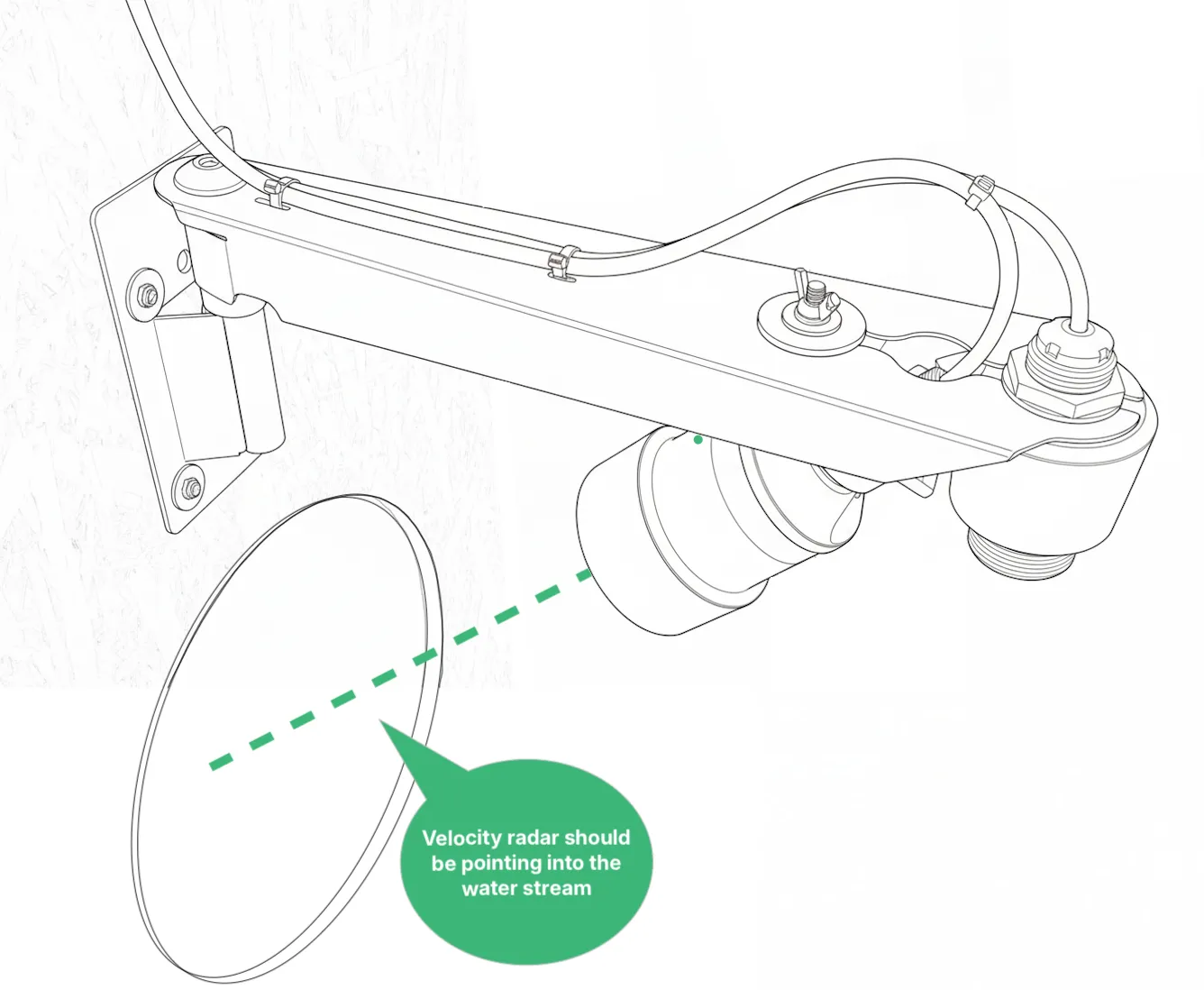
In this configuration, the surface velocity radar is mounted on the underside of the bracket to give a 45° angle. The surface velocity radar mount is attached to the bracket with the hand-operated locknut on top:
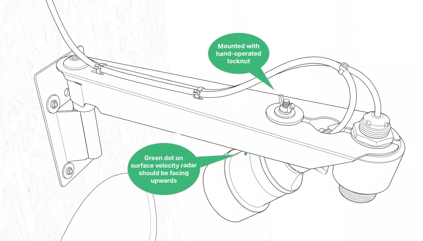
When mounting it, make sure the surface velocity radar points into the water stream:
Installation guidelines
Section titled “Installation guidelines”When installing the bracket, try to respect as many of the guidelines below as possible, in priority order. On some sites the geometry of the manhole doesn’t allow all guidelines to be respected at once, so focus on the highest-priority ones first.
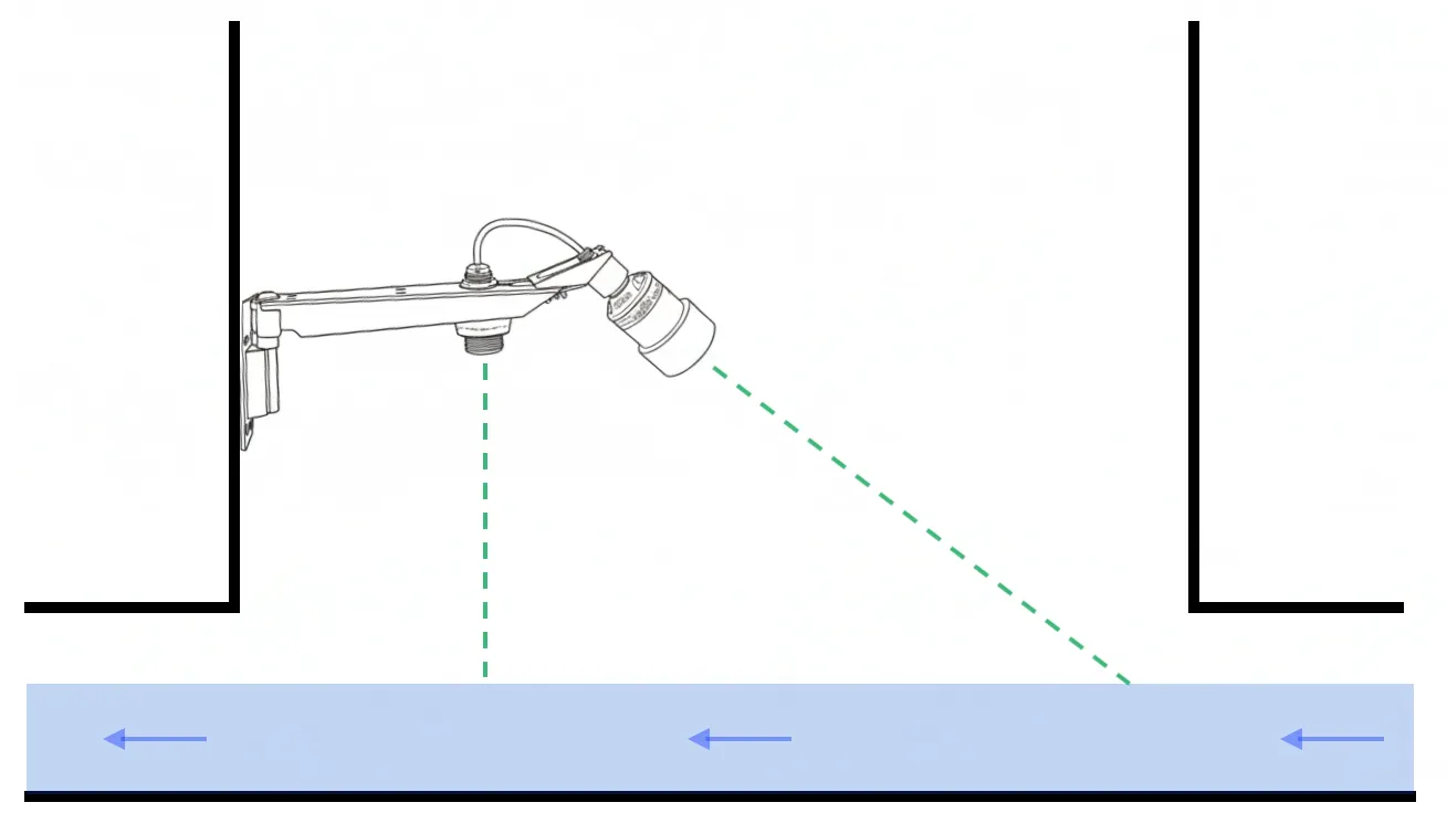
- The bracket should be placed low enough that the velocity radar’s line of sight points into the water stream, not the wall.
- The bracket should be completely level, so the level radar’s line of sight is perpendicular to the water surface.
- The bottom of the level radar should be at least 3 ft above the highest expected water surface, to provide a stable reading.
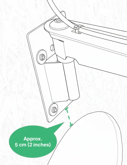
- The bottom of the bracket should be as close as possible to the perimeter of the pipe hole, to give the velocity radar the best field of view (while still respecting the other guidelines). If possible, place the bottom of the bracket panel on the wall approximately 5 cm (2 inches) above the top of the inlet pipe hole:
It’s possible to flip the orientation of the velocity radar and the bracket so it’s placed on the wall with the outlet instead (see 2.2 Alternative installation below). If more guidelines can be respected by doing so, switch to this alternative installation method.
2.2 Alternative installation: at the outlet, pointing towards the inlet
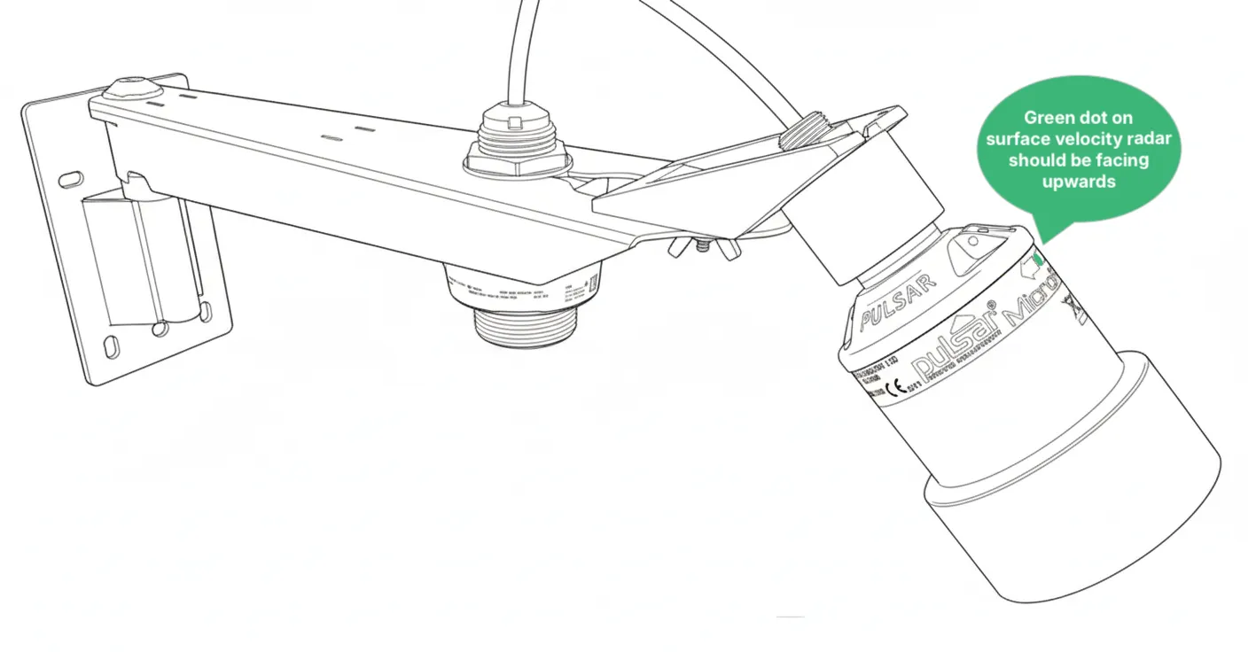
Section titled “2.2 Alternative installation: at the outlet, pointing towards the inlet”If the geometry of the manhole doesn’t allow you to install the bracket above the inlet as shown above, you can move the velocity radar mount to the top of the bracket instead. Here, the placement of the level radar and the velocity radar is swapped:
In this configuration, the bracket is installed above the outlet, pointing towards the inlet:
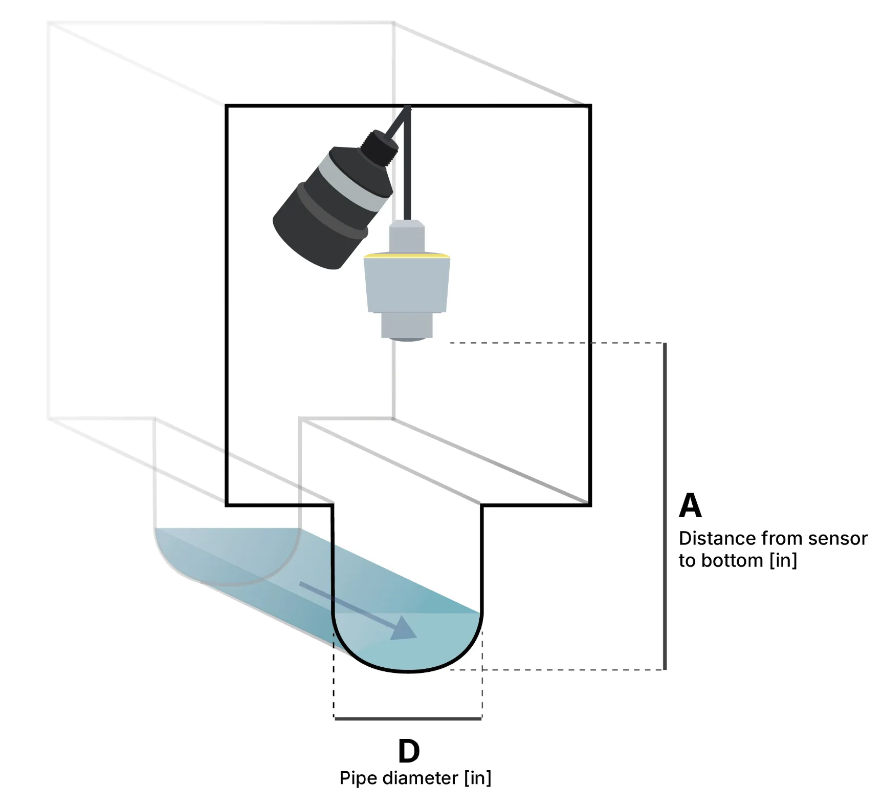
2.3 Record installation dimensions
Section titled “2.3 Record installation dimensions”After installing the bracket with the level and velocity radar, measure the exact installation height — the distance from the bottom of the level sensor to the bottom of the invert in the channel (dimension A below). Also measure or look up the pipe diameter (dimension D):