Installing the Level & Flow solution for Logger WD-68
Download as PDF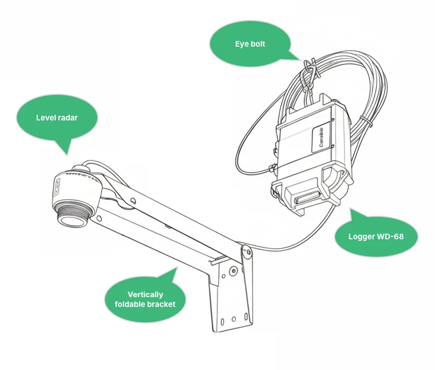
Equipment
Section titled “Equipment”The Consibio Level and Flow solution consists of all the equipment and accessories needed to install a level and flow monitoring system:
- Logger WD-68 battery-driven cellular datalogger
- VEGAPuls Level Radar
- Vertically foldable bracket for mounting the radar
- The bracket can be folded up if you need access to the manhole.
- Eyebolt for mounting the Logger
1. Activate Deploy Mode
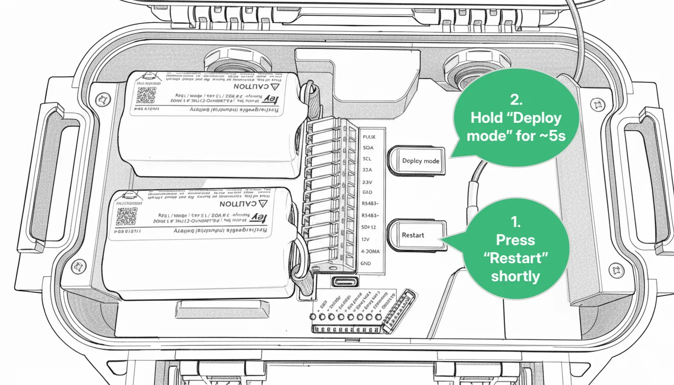
Section titled “1. Activate Deploy Mode”The first thing to do when arriving on the site of installation is to activate Deploy Mode on the Logger:
- Press Restart shortly.
- Hold Deploy Mode for approximately 5s. When the LEDs flash quickly one at a time in a repeating pattern, Deploy Mode is activated.
For the next 1 hour, the device will make a measurement every 30s and transmit every 5mins. After 1 hour, it will revert to the transmission and measurement interval configured in Consibio Cloud.
We activate this as the first step to make the Logger start connecting immediately, where it will scan the local network operators and select the most optimal one. On the first attempt, this can take some minutes.
2. Mounting instructions
Section titled “2. Mounting instructions”2.1 Mount the radar bracket
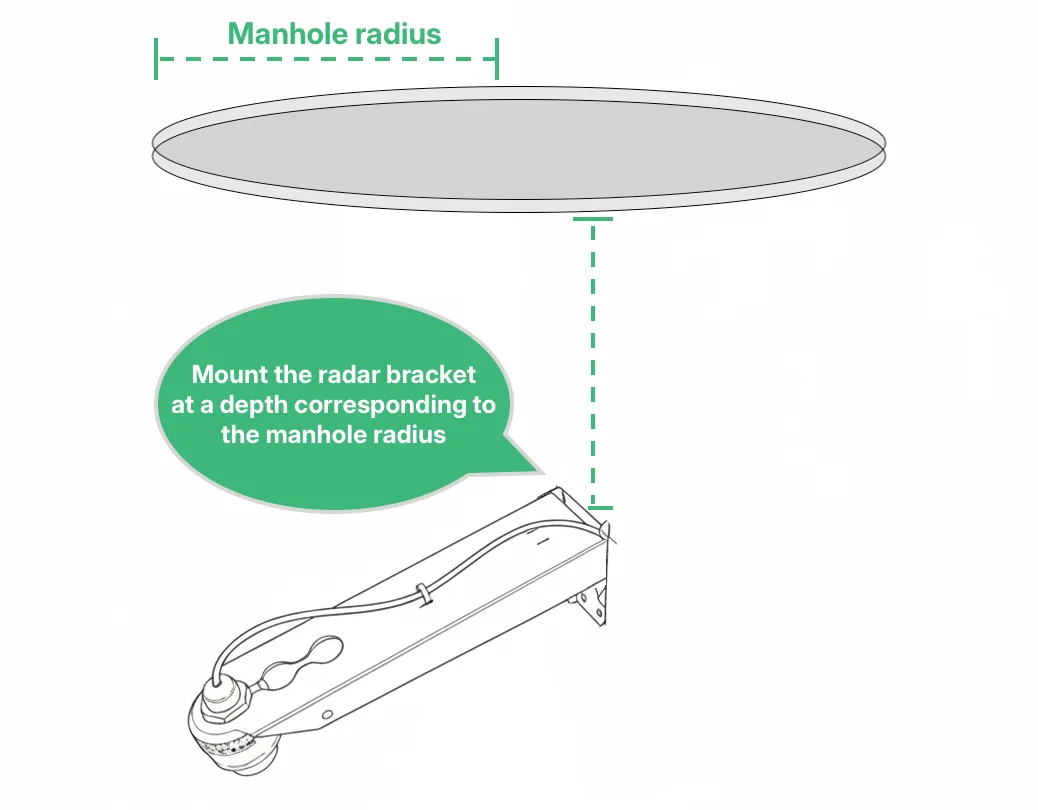
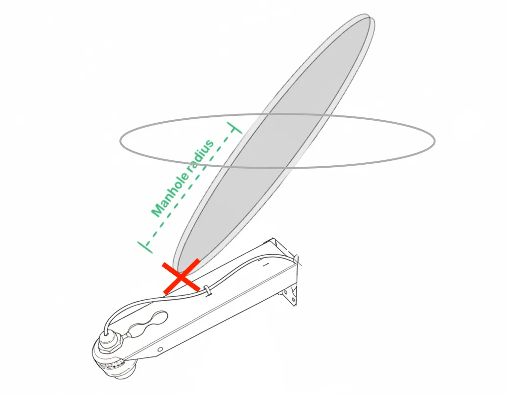
Section titled “2.1 Mount the radar bracket”Mount the bracket on the side of the manhole with the included wall plugs and bolts. Lower the top of the bracket by the manhole’s radius (e.g., 10“ for a 20“ diameter manhole) to prevent collision with the cover when it is tilted during opening it.
If it’s not practically possible to mount the radar bracket so far down, it should just be mounted as far down as possible.
Position the bracket on a position on the wall such that the radar mounting point faces directly down into the invert.
2.2 Mount the Logger
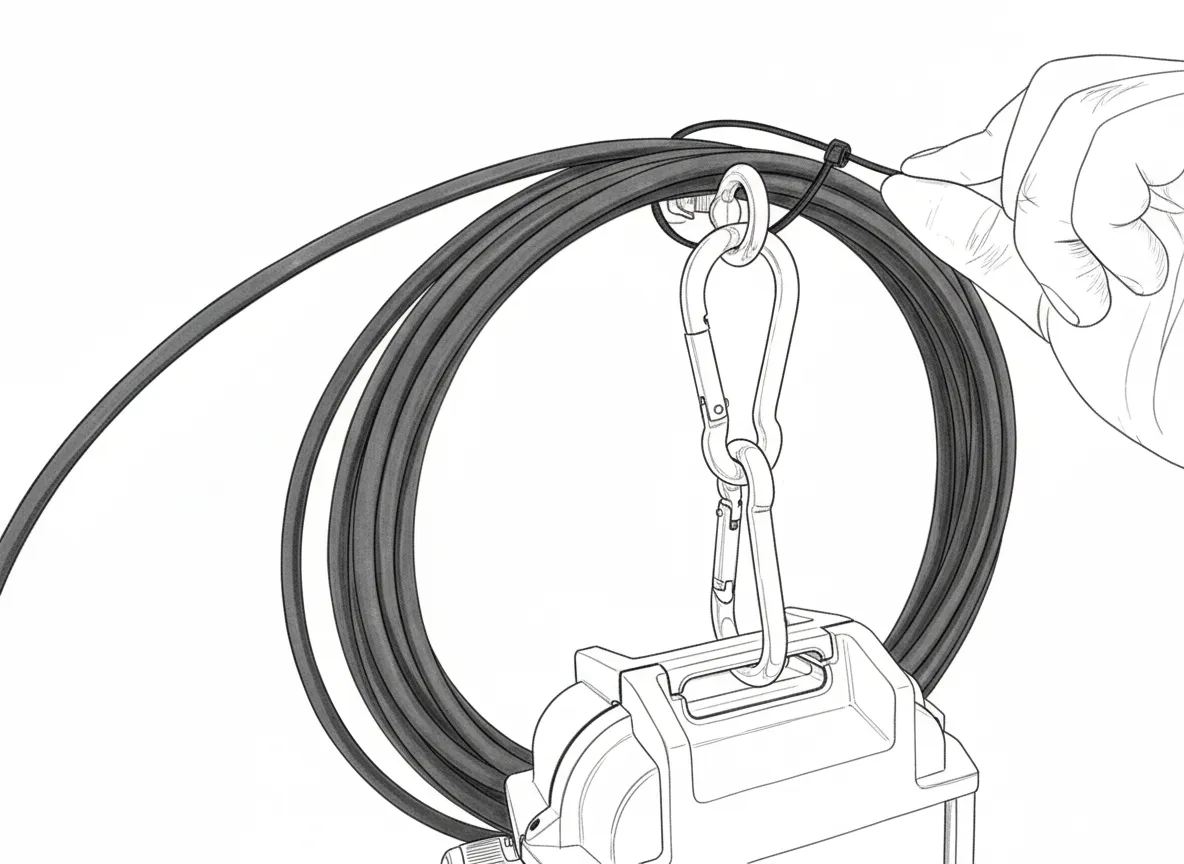
Section titled “2.2 Mount the Logger”Mount the Logger just below the manhole cover using the eyebolt and carabiners. This ensures optimal cellular reception and easy access for battery swaps.
Fasten the Logger to the eyebolt using the carabiners included with the Logger.
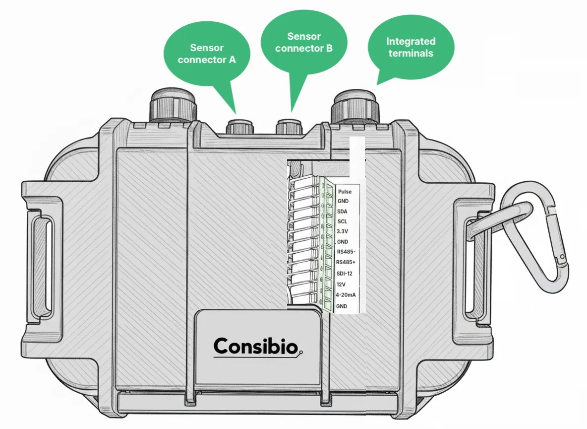
2.3 Mount and connect the level radar
Section titled “2.3 Mount and connect the level radar”Mount the level radar in the bracket and secure it with the included nut.
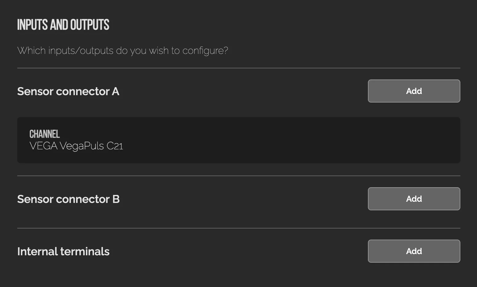
Connect the radar to one of the Logger’s sensor connectors.
Roll up any excess cable and tie it to the eyebolt behind the Logger.
2.4 Record installation dimensions
Section titled “2.4 Record installation dimensions”To calculate flow, we need 3 dimensions for the given site:
- A, Installation height — distance from sensor to bottom of invert (measured on-site).
- D, Pipe diameter — looked up in the documentation for the manhole.
- S, Slope of pipe — looked up for the manhole.
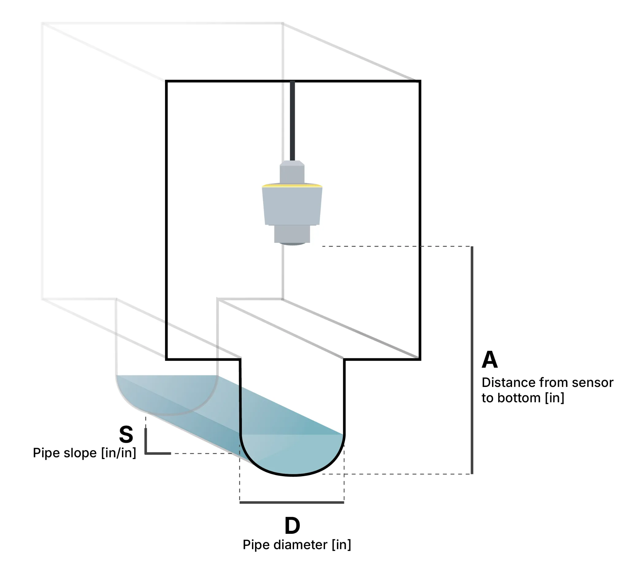
You need three different measures to properly calculate the flow from the sensor readings:
- A: The installation height, i.e. the distance from the bottom of the sensor to the bottom of the invert (in inches).
- D: The pipe diameter (in inches).
- S: The slope of the pipe (inch / inch).
The diameter (D) and the slope (S) can usually be looked up in the pipeline documentation.
The installation height (A) has to be measured manually after installing the sensor. It is very important that this measure is as accurate as possible, because it will directly affect the accuracy of the flow.
There are two ways to get an accurate installation height:
-
Most practical: measure the current water level with a long rod. After the device has been deployed, and you have ensured that it is transmitting while inside the manhole, put a long rod into the bottom of the manhole and pull it back up. Measure how far the rod was wetted and note down the exact time of the measurement.
Then, go to Consibio Cloud and check the distance output of the sensor (i.e. the distance from the sensor to the water surface).
The installation height (A) is the sum of these two measures:
A = water level [in] + distance [in] (at the same time of the water level measurement).
You are also more than welcome to send the measured water level and the time of measurement to our support team, and they will help set the rest up: support@consibio.com.
-
Less practical: direct measurement. If there is not much water in the pipe, and you are doing a confined space entry in the manhole, you can measure the distance between the bottom of the invert and the bottom of the sensor directly with a ruler or measuring tape.
When you have these measures, go to Virtual Sensors and enter them in the Virtual Sensor for flow calculation.
3. Verify installation and data quality
Section titled “3. Verify installation and data quality”After installation is done, put the manhole cover back on and wait 5 minutes.
We activated Deploy Mode in the first step, so the Logger will attempt to connect every 5 minutes. Before leaving the site, you should verify that the Logger transmits correctly through the manhole cover, so it’s important to wait for long enough to verify this.
Go to https://v3.consibio.cloud on a smartphone or laptop, log in to your project and check that data is coming in.
If you don’t get a signal after closing the manhole cover, you can install an external antenna.
Troubleshooting
Section titled “Troubleshooting”- No signal after closing the manhole cover — install an external antenna. Reach out to support@consibio.com if you need assistance.
- Flow readings look inaccurate — double-check the installation height (A), pipe diameter (D) and slope (S) entered in the Virtual Sensor; an inaccurate installation height is the most common cause of flow calculation errors.
Reach out to support@consibio.com if you need assistance.