

Logger 4WD
Download as PDFLogger 4WD is a battery-driven cellular datalogger for remote monitoring in a compact, weatherproof polycarbonate enclosure. It is sensor-agnostic and supports the most common industrial interfaces, so it can be used with any compatible sensor you might already own.
Logger 4WD shares its electronics platform with the Logger WD-68 — the same connectivity, power options, I/O and internal measurements — housed in a compact wall-mountable polycarbonate case.
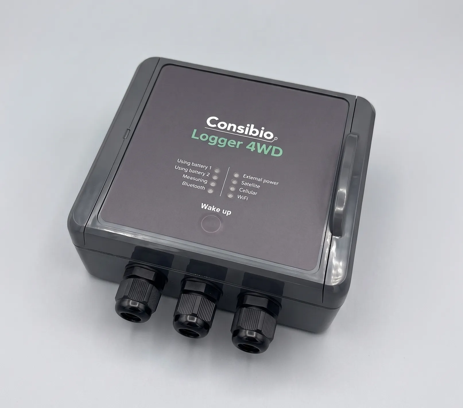
Specifications
Section titled “Specifications”Overall
Section titled “Overall”| Parameter | Value |
|---|---|
| Expected lifetime | +10 years |
| Guarantee | 1 year |
| Connectivity | Cellular: LTE Cat-M1, NB-IoT (eSIM included; a custom nanoSIM can be inserted). WiFi: 2.4 GHz (802.11 b/g/n). Add-on: Satellite. |
| Standards | DS/EN 61326-1:2013 |
Cellular
Section titled “Cellular”One of the most crucial parts of remote monitoring is robust connectivity, because it ensures that data is transmitted seamlessly and without interruption, allowing for real-time monitoring and analysis. Unreliable connectivity can result in lost or delayed data, which can significantly impact the effectiveness and quality of remote monitoring systems.
We have solved that by using unbranded SIM cards that operate across:
- 700+ vendors
- 180+ countries
in combination with an algorithm running on the Logger that periodically scans for the network with the best coverage. This means that if one vendor/network provider does not provide proper coverage or is temporarily out of service at the location of the datalogger, it will automatically detect it and select another network — and you don’t have to do anything.
This greatly reduces the risk of insufficient connectivity. Furthermore, all cost for SIMs, data etc. is included in a Consibio Cloud subscription.
Front panel and local interaction
Section titled “Front panel and local interaction”The front panel carries a set of status LEDs and a single Wake up button.
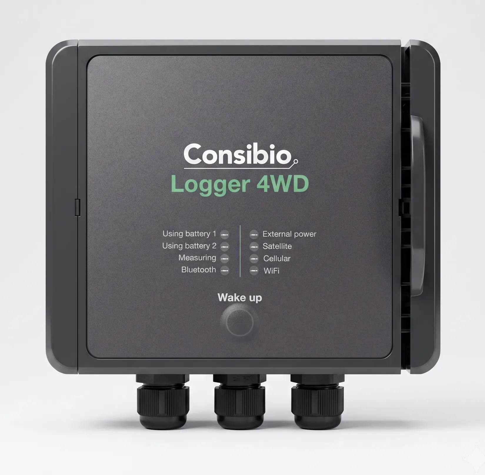
The LEDs give an at-a-glance overview of what the Logger is doing:
| LED | Indicates |
|---|---|
| Using battery 1 | The Logger is currently drawing power from battery port 1. |
| Using battery 2 | The Logger is currently drawing power from battery port 2. |
| Measuring | A measurement is in progress. |
| Bluetooth | Bluetooth is active for local configuration. |
| External power | The Logger is running on external power. |
| Satellite | Status of the optional satellite connection. |
| Cellular | Status of the cellular connection. |
| WiFi | Status of the WiFi connection. |
The datalogger has a single Wake up button on the front panel. It can be used in two ways:
- Short click: A short click on the button wakes up the device, it displays its current status on the LEDs and goes back to sleep.
- Press and hold: Pressing and holding the button until all LEDs flash one by one, the device goes online and sends collected datapoints to the backend, after which it goes back to sleep.
Mechanical
Section titled “Mechanical”| Parameter | Value |
|---|---|
| Operating conditions | –20°C to +50°C, 0–100% RH |
| Dimensions | 151 x 125 x 60 mm (L x W x H) |
| Housing material | Polycarbonate (UV and weather resistant); all components used are at least IP67-rated |
Enclosure
Section titled “Enclosure”The enclosure is made entirely of polycarbonate, making it UV and weather resistant. A hinged lid can be opened with a flat screwdriver and gives access to the electronics for maintenance, battery replacement or similar.
Antenna
Section titled “Antenna”An internal, flexible antenna is mounted on the underside of the hinged lid, providing both antenna protection and good signal strength. On request, the datalogger can be delivered with an external IP67-rated antenna, which is recommended when the Logger is installed inside a metal enclosure.
Electrical
Section titled “Electrical”Battery power options
Section titled “Battery power options”Logger 4WD has two battery ports. When the battery on port 1 is depleted, the Logger seamlessly switches to battery 2 and uses this instead.
The batteries are shipped with connectors that plug directly into the Logger, making them easily accessible and ensuring they can be swapped on-site within seconds without any tools.
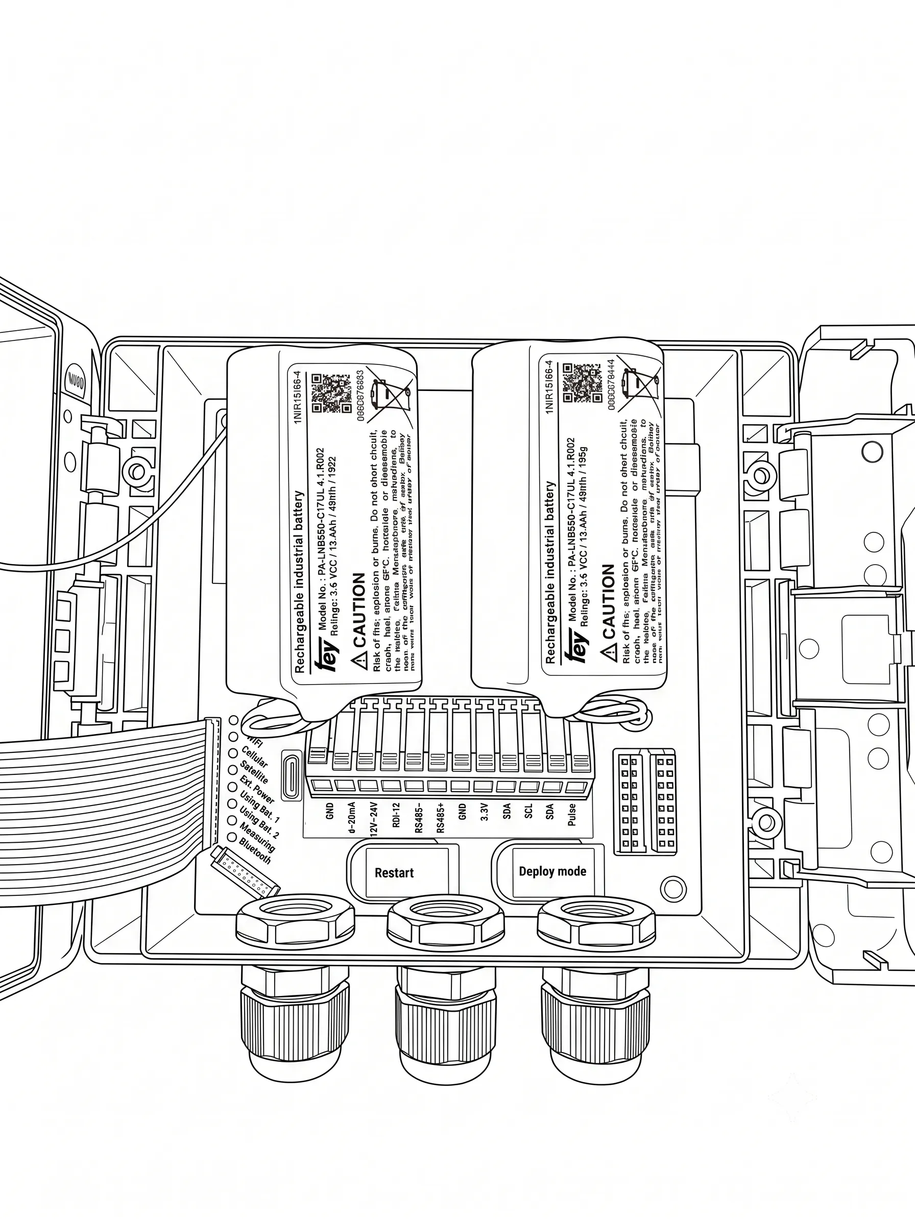
In the standard configuration, the Logger is shipped with two 48 Wh rechargeable Li-Ion batteries providing a very high battery capacity. An external battery charger is included with each Logger.
Spare batteries avoid downtime
Section titled “Spare batteries avoid downtime”If you have a set of spare batteries you can completely avoid downtime in the data collection by:
- Charging the spare batteries at the office.
- Going on-site and swapping the charged batteries with the existing ones.
- Bringing the depleted batteries home and recharging them.
See Charging the batteries for how to recharge a depleted battery pack.
| Rechargeable Li-ion Battery | SKU: 112009 |
|---|
Extremely low self-discharge with Li-SOCl2 batteries
Section titled “Extremely low self-discharge with Li-SOCl2 batteries”If the Loggers are used in a setup where you only need to measure and transmit very infrequently (e.g. once a day), you can achieve +5 years of battery life if the rechargeable Li-Ion batteries are replaced with non-rechargeable Li-SOCl2 batteries.
This is a different battery chemistry that has a much lower self-discharge, enabling them to function for many years where only a small amount of power is drawn. They cannot be recharged and must be replaced when depleted.
The LSH-20 Backup Battery is a 46 Wh Li-SOCl2 battery compatible with Logger 4WD with the same connector used for the rechargeable battery pack.
The LSH-20 Backup Battery can also be used in combination with a rechargeable battery to enable a setup with a rechargeable battery used as the primary power supply and the LSH-20 battery as a “backup” that doesn’t deplete itself unless used by the Logger.
| LSH-20 Backup Battery | SKU: 112004 |
|---|
Installing a solar panel
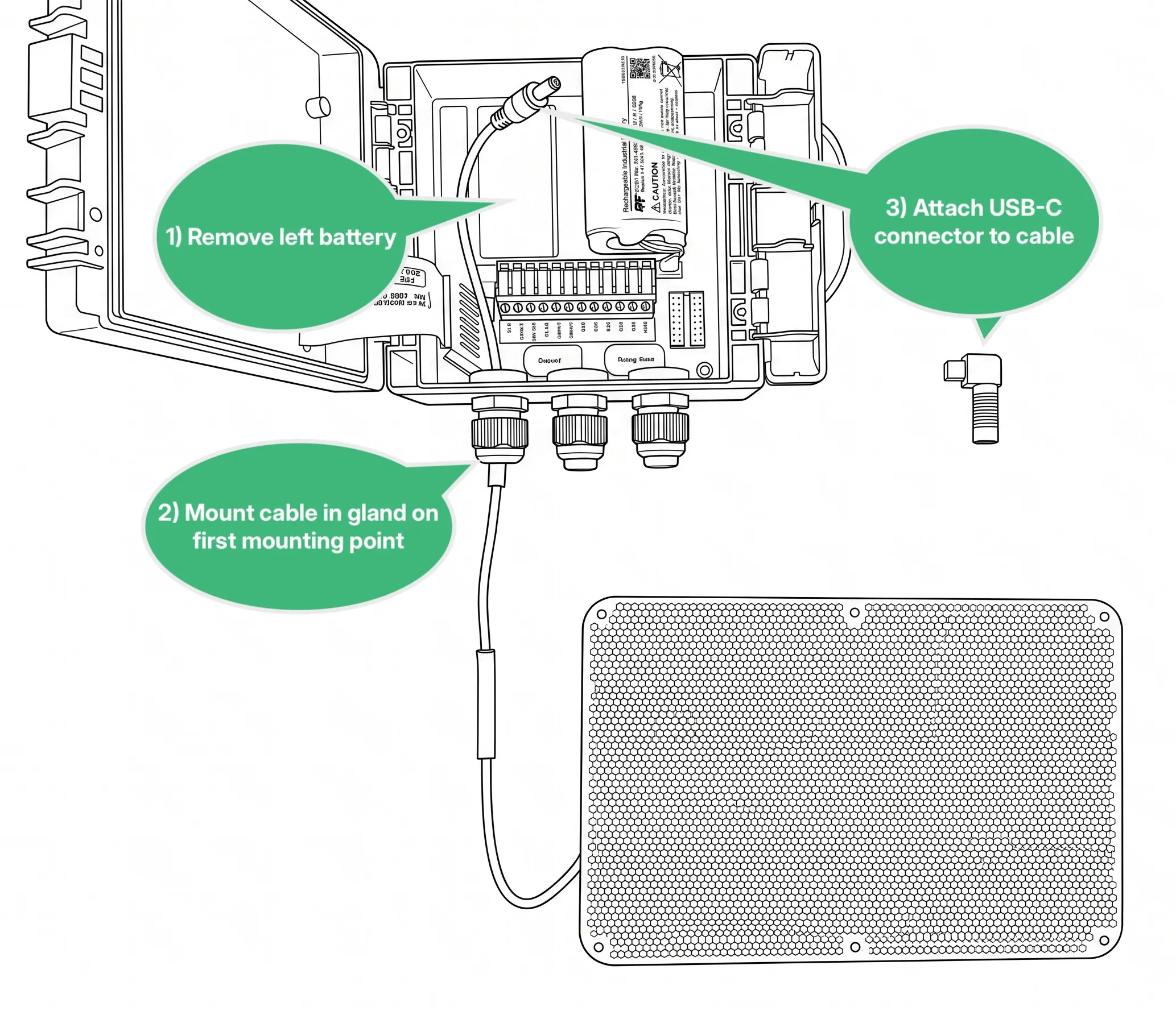
Section titled “Installing a solar panel”A solar panel can be connected to Logger 4WD to keep it powered from the sun. The panel’s cable is led into the enclosure through a cable gland and terminates in an angled USB-C connector that plugs into the Logger.
The angled connector needs room beside the USB-C port, so the left battery must be removed and the connector directed towards the now empty battery slot. The Logger runs on the remaining battery, which the solar panel keeps charged — see Charging the batteries.
-
Open the hinged lid and remove the left battery.
-
Mount the solar panel cable in the gland on the first mounting point.
-
Attach the angled USB-C connector to the cable.
-
Attach the USB-C connector to the Logger, with the angle directed towards the now empty battery slot.
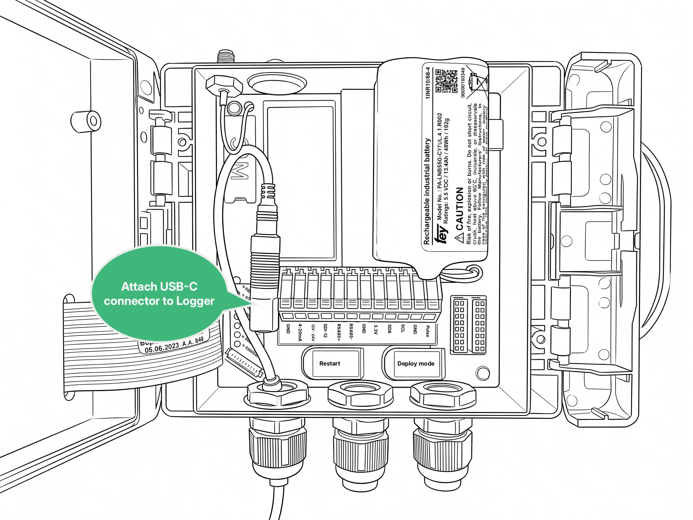
Using the USB adapter cable is the same setup: remove the left battery, mount the cable in the gland and attach the angled USB-C connector to the Logger, directed towards the empty battery slot.
I/O and sensor connections
Section titled “I/O and sensor connections”Logger 4WD supports all the most common interfacing options and protocols.
| I/O | Description |
|---|---|
| ModbusRTU / RS485 | ModbusRTU over RS485. Can be used with any ModbusRTU sensor. Multiple sensors can be connected to the same port if they have different addresses. |
| SDI-12 | Connect to SDI-12 compatible sensors. Multiple sensors can be connected to the same port if they have different addresses. |
| 4-20mA | Sample a 4-20mA signal from an analog sensor. In a two-wire setup, connect 12V to sensor (+) and connect the return path (-) to the 4-20mA input. |
| Pulse counter / Wake signal | Count pulses from relays, float switches, rain gauges, NPN sensors etc. This is a dry signal input that measures if a connection between this terminal and GND is closed or open. Can also be used to wake the Logger from deep sleep and perform a measurement outside the configured schedule. |
| 3.3V power output | 3.3V voltage output to power low-power sensors and peripherals. Max current: 500 mA |
| 12V/24V power output | Standard power output to power sensors and peripherals. It can be configured to either 12V or 24V depending on the configuration in the cloud Max current: 12V: 150 mA 24V: 75mA |
The Logger has 3 parallel ports, which all contain the input/output options listed above. This means that the Logger can support up to three parallel connections of the same type without signal conflicts. This can be used to connect e.g. three 4-20mA analog sensors, three ModbusRTU devices with the same address or similar.
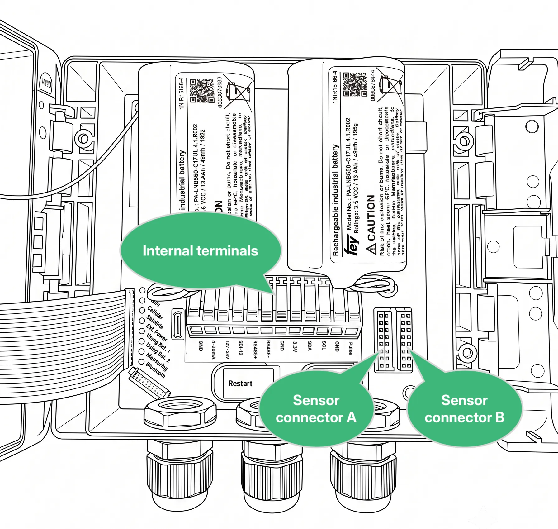
Furthermore, the integrated terminals can be used to easily connect custom sensors without a connector. Logger 4WD is sensor-agnostic and can be used with any compatible sensor you might already own.
Using Sensor Connector A and B
Section titled “Using Sensor Connector A and B”Sensor connector A and B are spring-loaded push-in connectors, that allows you to connect a pre-crimped wire by simply pushing it into the connection. See below for pin assignments in the two connectors.
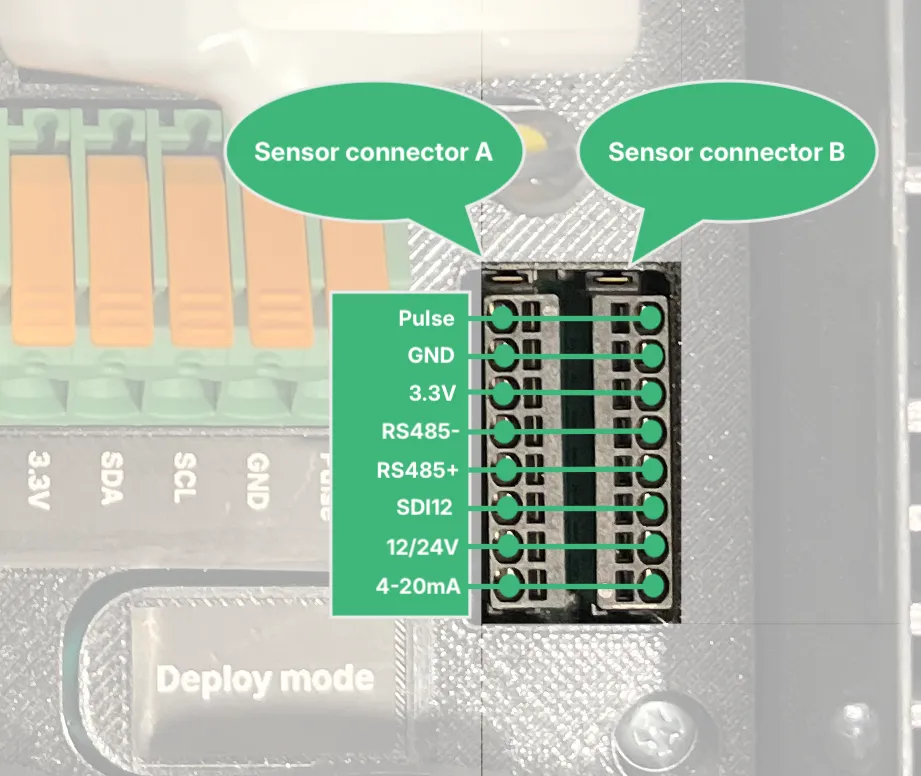
We advise that the wires used in these connectors are crimped with a ferrule like this one from Phoenix Contact AI 0,14- 6 GY. After crimping, the wire can be inserted into the circular holes (marked with green above). To unload a connected wire, insert a small flathead screwdriver in the rectangular hole in the connector to disengage the internal spring load and pull out the wire.
Internal measurements
Section titled “Internal measurements”The datalogger monitors several parameters internally, which are automatically reported to Consibio Cloud.
| Parameter | Description |
|---|---|
| Temperature and humidity | Logger 4WD has a built-in temperature and humidity sensor. This makes it possible to remotely monitor that the internal electronics are not exposed to conditions outside the recommended ranges. The humidity sensor also ensures that risk of condensation can be registered and alerted to the backend before the electronics are affected, to ease the troubleshooting process. Temperature sensor: Range –40° to +125°C, Accuracy 0.2°C. Humidity sensor: Range 0 to 100% RH, Accuracy 1.8% RH. |
| Barometric pressure | The internal barometric pressure of the Logger is continuously measured. A pressure relief valve inside the enclosure ensures that the pressure inside the Logger is the same as the surroundings. This can be used to measure barometric pressure directly (for weather monitoring), but can also be used for automated pressure compensation of absolute pressure transducers. Sensor: Range 300 to 1250 mbar, Accuracy 0.5 mbar (worst-case). |
| Tilt and orientation | An internal accelerometer ensures that the Logger is always aware of its own orientation in 3D space. Thus, the Logger itself can be used as an inclinometer. It can also be used to generate automated alerts if the Logger is mounted on a structure that might be knocked over in traffic or similar. |
| Battery gauging | The Logger continuously monitors the actual state of charge of both the rechargeable battery and backup battery. This is used to monitor battery state from the backend and generate alerts when it is almost depleted, but also to alter operation to prioritize power over performance in situations where it is needed. |
Power consumption and battery lifetime
Section titled “Power consumption and battery lifetime”The Logger has 3 operational states, which have very different power consumptions:
| State | Description | Power consumption (typical) |
|---|---|---|
| Deep sleep | When the Logger is not actively performing a measurement or transmitting data, it goes to deep sleep to preserve power. In most configurations, it spends most of its time in deep sleep. | 0.2 mW |
| Measurement | The Logger periodically wakes up to perform a measurement, save the result in its internal flash storage and then go back to sleep. The power consumption during measurement depends a lot on the type of sensors connected. | 150 to 500 mW |
| Transmission | Transmission is by far the largest power consumer, and thus often dictates the battery lifetime. | 1600 mW |
The user can configure the measurement interval and the transmission interval for each Logger through Consibio Cloud. These settings dictate how much time the Logger spends in each state and thus the effective battery life.
Because Logger 4WD uses the same electronics and battery packs as the Logger WD-68, the battery-lifetime estimates and discharge curves shown for that model apply here as well. The transmission power and time depend highly on the quality of the cellular connection and can thus vary significantly if connectivity is very poor.