

Setting up the WD Output Module
Download as PDFThe WD Output Module is an expansion module for Logger WD-68. It turns the Logger from a device that only reports measurements into one that can also act on them — locally on the Logger, and remotely from Consibio Cloud.
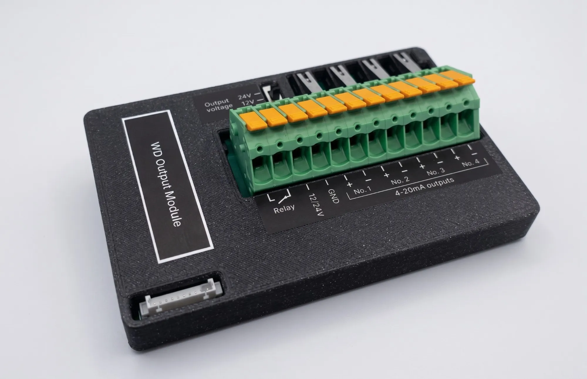
The module provides:
- One relay output that switches the connection between the two Relay terminals. It is a low-power output rated for 30V and 100 mA, so use it to switch a signal line, or to drive the coil of a contactor or larger relay that in turn switches a pump, a valve or a light.
- Four 4-20mA outputs that can drive a 4-20mA signal to a PLC, SCADA system, frequency converter or any other device with a 4-20mA input.
- A 12V or 24V supply output on the 12/24V terminal, which you select with a switch on the module.
- Wiring test buttons that let you verify each 4-20mA loop on-site, without waiting for the Logger to transmit.
Each output is mapped to an element in Consibio Cloud, so the outputs can be driven by an automation rule running on the Logger.
Before you start
Section titled “Before you start”- A Logger WD-68 with a free expansion port and the cable included with the module.
- Firmware on the Logger:
- 3.14.0 or newer to select the expansion type and use the relay output.
- 3.15.1 or newer to use the 4-20mA outputs.
- Edit permissions on the project in Consibio Cloud.
1. Install the module in the Logger
Section titled “1. Install the module in the Logger”The module is designed to sit in the lid of the Logger WD-68 enclosure, where it stays clear of the batteries and the internal terminals.
- Open the lid of the Logger.
- Peel the backing off the velcro strips on the back of the module and press the module firmly against the inside of the lid.
- Connect the included cable between the Connector on the module and the Expansion Connector on the Logger board. Route the cable through the cable guide so it isn’t pinched when the lid closes.
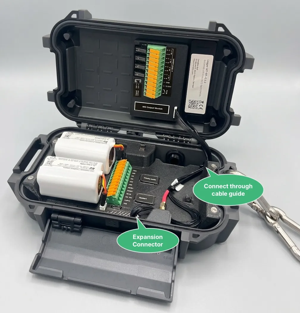
Close the lid and check that the cable is not trapped in the gasket — the Logger only keeps its IP rating if the lid seals properly.
2. Parts of the module
Section titled “2. Parts of the module”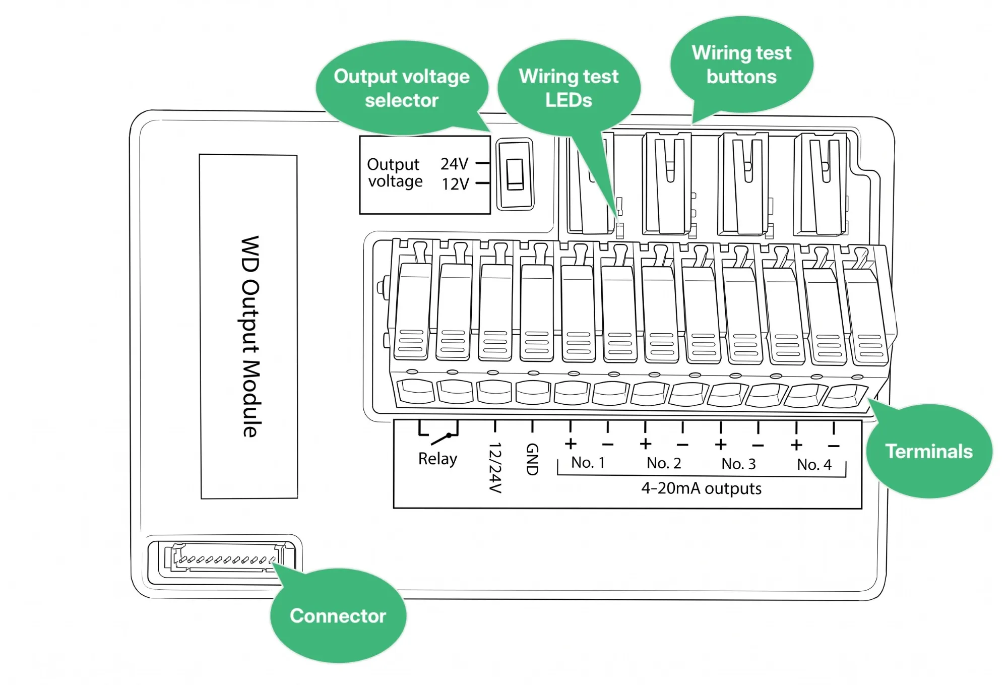
| Part | Description |
|---|---|
| Connector | Connects the module to the expansion connector on the Logger using the included cable. This is both the power supply and the data connection for the module. |
| Output voltage selector | Selects whether 12V or 24V is generated on the 12/24V terminal. Set it before wiring anything to that terminal. |
| Terminals | The 12-pole pluggable terminal block that carries the relay output, the supply output and the four 4-20mA outputs. |
| Wiring test buttons | One button per 4-20mA output. Press a button to test whether that loop is wired correctly. |
| Wiring test LEDs | The LED next to a test button lights up while the button is pressed if the corresponding 4-20mA loop is wired correctly. |
Terminals
Section titled “Terminals”The terminals are numbered from left to right, with the terminal block facing you as in the drawing above:
| No. | Terminal | Description |
|---|---|---|
| 1 | Relay | Relay terminal 1 |
| 2 | Relay | Relay terminal 2 |
| 3 | 12/24V | Supply output, 12V or 24V as chosen with the output voltage selector |
| 4 | GND | Ground, common with the Logger |
| 5 | No. 1 + | 4-20mA output no. 1, positive |
| 6 | No. 1 – | 4-20mA output no. 1, negative |
| 7 | No. 2 + | 4-20mA output no. 2, positive |
| 8 | No. 2 – | 4-20mA output no. 2, negative |
| 9 | No. 3 + | 4-20mA output no. 3, positive |
| 10 | No. 3 – | 4-20mA output no. 3, negative |
| 11 | No. 4 + | 4-20mA output no. 4, positive |
| 12 | No. 4 – | 4-20mA output no. 4, negative |
The terminal block is pluggable: pull it out of the module, wire it on the bench, and plug it back in when you’re done.
3. Wire the relay output
Section titled “3. Wire the relay output”The relay switches the connection between the two Relay terminals (terminals 1 and 2). The relay itself doesn’t supply any power — it only opens and closes the circuit you wire through it, exactly like a switch.
Ratings
Section titled “Ratings”| Parameter | Value |
|---|---|
| Maximum switching voltage | 30V |
| Maximum continuous current | 100 mA |
Switch an external power source
Section titled “Switch an external power source”To switch an external power source within the ratings above, break the supply line and run it through the two relay terminals:
- Wire the positive conductor from the external power source to Relay terminal 1.
- Wire Relay terminal 2 on to the positive input of the equipment you want to switch.
- Wire the return conductor from the equipment directly back to the external power source — it does not pass through the module.
When the relay is closed, the circuit is complete and the equipment is powered. When it is open, the circuit is broken.
4. Wire the 4-20mA outputs
Section titled “4. Wire the 4-20mA outputs”The four 4-20mA outputs are passive (loop-powered): the module regulates how much current flows through the loop, but it does not supply the loop with power. The loop needs an external power supply, which is normally the device that receives the signal (a PLC or SCADA input, for example).
Wire a passive loop
Section titled “Wire a passive loop”For each output you want to use:
- Wire the positive terminal of the loop power supply to the + terminal of the output (terminal 5, 7, 9 or 11).
- Wire the – terminal of the output (terminal 6, 8, 10 or 12) to the positive input of the receiving device.
- Wire the negative input of the receiving device back to the negative terminal (0V) of the loop power supply.
The module, the receiving device and the power supply are now in series in a single loop. Watch the polarity: the module only regulates current that flows into + and out of –.
Drive a loop actively
Section titled “Drive a loop actively”If the receiving device cannot supply the loop, you can power the loop from the module itself by using the 12/24V output as the loop supply:
- Set the output voltage selector to the voltage the loop needs (12V or 24V).
- Fit a jumper wire from the 12/24V terminal (terminal 3) to the + terminal of the output you want to use.
- Wire the – terminal of that output to the positive input of the receiving device.
- Wire the negative input of the receiving device back to the GND terminal (terminal 4).
Test the wiring
Section titled “Test the wiring”Each 4-20mA output has a wiring test button with an LED next to it. Press the button for an output: if the LED lights up, that loop is complete and wired with the correct polarity. If the LED stays dark, the loop is broken or reversed.
Check the following if an LED stays dark:
- The + and – wires are swapped.
- The loop power supply is off, or the receiving device does not power the loop.
- A wire is loose in the terminal block, or the terminal block is not fully plugged into the module.
- For an actively driven loop: the jumper between 12/24V and the + terminal is missing, or the return wire does not reach GND.
Test each loop before closing the Logger — it is much faster than diagnosing the wiring from Consibio Cloud afterwards.
5. Configure the expansion module in Consibio Cloud
Section titled “5. Configure the expansion module in Consibio Cloud”Before the Logger uses the module, you have to tell it that an Output Module is connected.
- Go to v3.consibio.cloud and open your project.
- Open Devices and select the Logger the module is connected to. See Claiming a device if the Logger is not in your project yet.
- Scroll down to Inputs and outputs. The Logger’s inputs and outputs are grouped into Sensor connector A, Sensor connector B, Internal terminals and Expansion.
- Next to Expansion, select Expansion type and choose Output Module. Save.
An Add button appears under Expansion once the expansion type is set.
6. Set up the relay output channel
Section titled “6. Set up the relay output channel”- Under Expansion, select Add.
- In Select channel type, choose Relay output.
- In the Relay state row, use Send to element to select the element that should control the relay, or create a new one.
- Select Save.
The relay state is expressed as a percentage:
- 50% or above closes the relay.
- Below 50% opens the relay.
7. Set up the 4-20mA output channels
Section titled “7. Set up the 4-20mA output channels”All four 4-20mA outputs are configured in one channel.
- Under Expansion, select Add.
- In Select channel type, choose 4-20mA outputs. The channel has four sub-channels: 4-20mA output no. 1 to 4-20mA output no. 4, matching the terminal labels on the module.
- For each output you have wired, use Send to element to select the element that should drive it, or create a new one. Leave the outputs you are not using empty.
- Optionally set Parameter type and Base unit for each output, so the value is shown with the right unit in Consibio Cloud.
- Select Save.
The output value is expressed as a percentage of the 4-20mA span:
| Value | Current |
|---|---|
| 0% | 4 mA |
| 50% | 12 mA |
| 100% | 20 mA |
Values outside 0-100% are limited to the nearest end of the range.
Two special cases are worth knowing:
- If the element mapped to an output has no value, the module drives 3.7 mA. This is the transmitter failure signal defined by NAMUR NE43, so the receiving device can tell a missing value apart from a genuine 4 mA reading.
- If an output has no element assigned, it is not driven at all, and a loop wired to it reads 0 mA.
8. Drive the outputs
Section titled “8. Drive the outputs”When you map a sub-channel of the Output Module to an element, that element becomes an output element in Consibio Cloud. Output elements are driven by an automation rule, which you set up in the project and point at the element through its Output element setting. In the rule’s Output type setting, you choose how the output is determined:
- Fixed output — outputs a value you define, optionally following a dynamic sequence over time.
- On/Off controller — switches the output depending on whether a measured value is above or below a setpoint, with a configurable deadzone.
- PID controller — regulates the output continuously towards a setpoint.
- Triggered pulse output — sets the output to 100% for a short period when a measured value crosses a threshold.
- Follow sensor — makes the output follow a measured value proportionally. See Making an output follow a sensor.
Automation rules run locally on the Logger, so the outputs keep working between transmissions and while the Logger is offline.
Troubleshooting
Section titled “Troubleshooting”- A wiring test LED stays dark — the loop is broken or the polarity is reversed. See Test the wiring.
- The receiving device reads 3.7 mA — the element mapped to that output has no value. Check that an automation rule is driving the element.
- A wired loop reads 0 mA — the output has no element assigned in the 4-20mA outputs channel.
- The channel type is missing from the dropdown — the Logger’s firmware is older than the version the channel requires (3.14.0 for the relay output, 3.15.1 for the 4-20mA outputs).
- The relay doesn’t switch, or a channel reports an error — the Logger cannot reach the module. Check that the cable is fully seated in both the module’s connector and the Logger’s expansion connector, and that Expansion type is set to Output Module.
Reach out to support@consibio.com if you need assistance.